Figure 6.1: Distributed Control System
Final Report: Arachnae II
Robot Control System Architecture |
Arachnae II is a relatively complex robot. At the time of this writing it reads 11 sensor signals and actuates 6 legs comprising 18 servo motors which gives the machine a total of 21 degree of freedoms. Keeping this mechanical complexity in mind it is obvious that the control system has to be designed so, that it makes the the control of the robot manageable. That is why we divided the controller system into smart subsystems each responsible for a specific part of the computing and linked them together with a low speed serial network (simple two-wire 2400 baud rs232c links). Following the suggestions in [24, Ferrell] we made each leg and the body an individual subsystems with its own controllers and sensory. As shown in figure 6.2, Arachnae II is organized with a central coordination processor (MCP) to which the two subsystems motion control and sensory processing are attached (the final design will have 7 subsystems). Calculation for step sequences, gait control and reading sensor data is then handled locally in the according processor nodes with only high level communication on the serial network.
After we have chosen a proper leg design, the remaining question is, how to actuate and
control them.
For Arachnae II we decided to use and implement a so-called distributed system which has a
lot of advantages over a single-processor solution. A good introduction and discussion of
distributed system can be found in [19, George Coulouris et al].
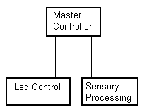
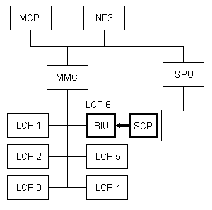
The fundamental arcitecture designed for the control of Arachnae is as follows:
Figure 6.1: Distributed Control System
The Master Controller is meant as supervisor of all the events on the distributed network. It does no relevant computing for step sequences or sensor readings.
The actual computation for proper gaits and step sequences is performed in the Master Motion Controller which itself is the master for its underlying 'Legs Network'. Results are sent to the Leg Control Processors which themselves calculate a trajectory corresponding to the required step sequence.
The Sensory Processing Unit on the other hand is both responsible for requesting sensor readings from an adequate sensor and testing the returned data for validity.
See a more detailed overview of the currently implemented controllers and their internetworkings in figure 6.2:
Figure 6.2: Detailed overview of Control System
In the following paragraphs are brief descriptions of the functionality and types of messages sent to and received from each processor nodes in the network.
Type: level 0 node, Address: 0x01, Status: necessary
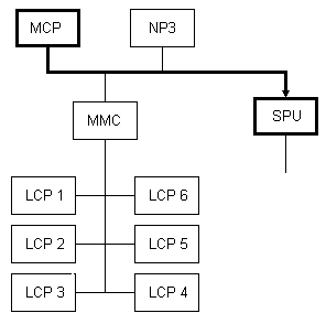
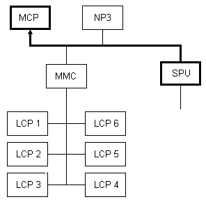
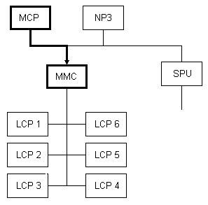
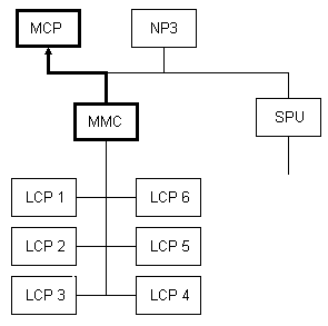
The MCP is a coordinationprocessor that is responsible for initializing and message scheduling. After a systemstart (turn on or reset) the MCP resets the connected processors (MMC and SPU. These processors are reseting the other processors). The main purpose is message scheduling. The MCP contacts the SPU (Sensor Processing Unit). After that, the SPU sends sensor-data and the MCP has to do something reasonable with it, that means that the message to the MMC (Master Motion Controller) depends on the SPU-data.
Type: level 0 node, Address: 0x04, Status: necessary
The SPU is initialized by a resetprocedure from the MCP. The SPU is responsible for all connected sensors. The SPU receives data from the sensors and sends it to the MCP. The MCP "knows" what it is to do with this sensor-data.
 |
|
 |
|
Type: level 0 node, Address: 0x03, Status: necessary
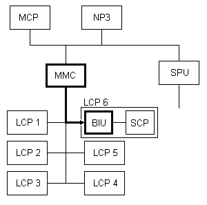
The MMC is initialized by a resetprocedure from the MCP. The MMC gets some movecommands from the MCP. After that, the MMC sends commands to the BIU's. Every leg has a BIU and a SCP. These two processors (BIU and SCP) are responsible for the moves (lift, back, ahead and down) of one leg. The MMC is responsible for the right sequence of one step.
 |
|
 |
|
Type: level 0 node, Address: 0x00 - 0x06, Status: necessary
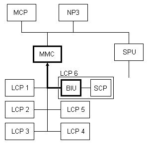
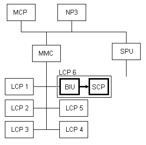
The BIU's (each leg has one BIU) is initialized by a resetprocedure from the MMC. The BIU's are connected with the MMC and are responsible for message scheduling. The MMC sends a command to a BIU and the BIU sends a message to the connected SCP. A SCP of a leg is connected to the servos of a leg.
 |
|
 |
|
Type: level 0 node, Address: -, Status: necessary
Each leg has a SCP, that is connected with the servos and the BIU of a leg. The SCP is responsible for controlling the servos. The SCP gets a command from the BIU and depending on the message from the BIU it realizes the command with help of the servos. An address is not necessary, because a SCP is only connected with a BIU from one leg.
 |
|
 |
|
![]()
Last updated: 26.6.1999