Figure 7.1: Schematic of Arachnae II's controller network
Final Report: Arachnae II
Electrical Subsystems |
The robot control system is divided into smart subsystems all linked together with a low speed serial network (two-wire 2400 baud rs232c). This design allows local processing with relatively small and cheap controllers where it is needed. High level communication on the serial network is only on demand.
The following paragraphs gives an indepth description of each subsystem or node in the network.
All of the controllers used are members of the Parallax Basic Stamp family, namely Basic Stamp 1 for those tasks which doesn't require high performance or many I/O ports whereas the Basic Stamp 2/SX is used for functions with either high performance demands or needs for higher number of I/O ports.
Figure7.1 below gives an overview of the fundamental structure of the complete controller network whereas figure 7.2 shows the arrangement of the several nodes on the robot itself.
Figure 7.1: Schematic of Arachnae II's controller network
Figure 7.2: Arrangement of controllers and sensory on Arachnae II's body
The subsystems interconnection is formed by a two-wire 2400 baud serial communication
line.
Though the line is fast enough at the moment to transmit the few bytes per command it is
planned to replace this low speed communication line by a somewhat faster RS485/422 serial
bus. This will be necessary on the implementation and usage of a ultra sonic range system
at the latest.
Not really a node which performs any useful tasks it serves as a stabilizer for the two
supply voltages for controllers and servo motors. It simply consists of a pcb with a few
power supply connectors and two 2200 uF capacitors on it.
See here a photo.
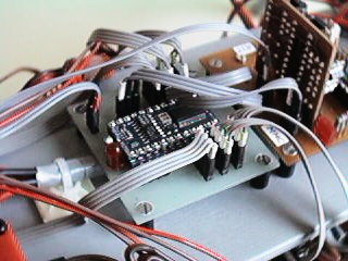
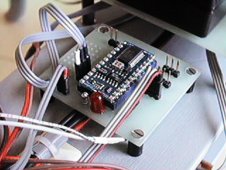
The Master Control Processor actually is a Basic Stamp 1 scalable with a second
controller of the same type to increase computing performance if needed.
This subsystem serves only as a supervisor for its underlying network, that is, it both
administers the network and schedules messages to the proper target systems.
For the future it is planned to implement all the behavioral computation on it.
See here a photo of the mcp.
The Master Motion Controller is a satellite controller with two responsibilites. The
first is to receive global locomotion commands via MCP from the
navigational subsystem NP3 and compute suitable step sequences. The
second is to send the result to its six subordinated leg control processors
which then actuates the servo motors.
The controller itself is a Basic Stamp 2/SX due to the high performance requirements.
See here a photo of the MMC.
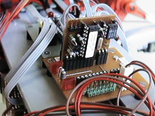
The Leg Control Processor is actually built of two separate controller boards. One
Basic Stamp 1 acting as a bus interface controller (biu) and one servo control processor
(scp) consisting of a Basic Stamp 2/SX. The biu connects to the serial interface and both
receives step/gait commands from and transmits acknowledge and error messages back to the
master motion controller. It checks the received data for validity and sends them over a
local serial high speed bus to the scp. This receives the step commands, computes a proper
trajectory based on the command information and actuates the three servos for its leg. If
an error situation occures it is sent back to the mmc.
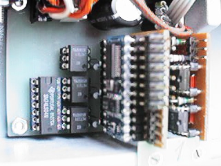
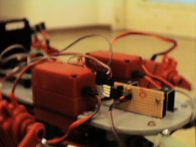
See here a photo of a lcp. At the right is the bus interface unit biu followed by the servo
control processor scp at the left. The two controller boards are mounted on a backplane
which also holds the servo driver unit circuitry sdu.
Working as a slave to the master control processr the sensor processing unit or spu
serves as a master for its undelying network of dedicated sensor subsystems.
It receives requests for sensor readings either from the navigational
subsystem np3 or from the master control processor. If a data
request is received it checks the address and sends a communication request itself on the
serial line. The addressed sensor subsystem performs the reading and, if necessary, a
precalculation and returns the result. The spu itself checks the result for validity
concerning limits and ranges and transmits either the preprocessed data or an error
message if something failed.
See here a phot of the spu.
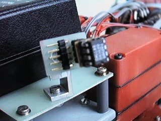
The Tactile Proximity Sensor Controller tpsc is the last hope if all other range
detecting sensors like usrc and iirc fails by any
reason. It detects any collision with obstacles in its drive way by using a bunch of
feelers or 'whiskers' which passively scans the space up to 20 cm before the robots head.
Though the sensor system can handle up to eight feelers at once only four are used at the
moment.
The program runs as a task in the spu.
See here a photo of the sensor subsystem
while here is a detailed view of a single feeler.
The ultra sonic range controller is based on a polaroid 6500 sonar device controlled by a Basic Stamp 2 due to the rigid timing constraints. Though not implemented yet it is designed and constructed.
The infrared range controller subsystem consists of two sharp gp2d02 distance measuring sensors mounted at
the head of the robot.
Though the sensors were actually part of the first implementation of the sensory they are
not implemented yet due to problems on bringing them to work (that is, to return measures
others than always 255).
Another important part of a mobile robot. A tilt sensor measures the current magnitude
of inclination which may be useful on avoiding dangerous situations while walking on
slopes.
Though already designed and built-up it is not implemented yet. The chosen design has a
very low resolution, that is, it checks only for exceeding a certain inclination (preset
to 15° on x and y in the plane).
Used for behavioral algorithms. Any robot which shall behave like an insect must have
some sort of reactive and reflexive way of acting. One of these is performed by a certain
reaction to ambient temperature (we call this K-phobic and K-tropic). To simplify the
design of the sensor system we used an integrated, programmable thermometer/thermostat
chip 1620 from Dallas Semiconductor.
The program runs as a task in the spu.
See here a photo of one of the two sensors
mounted on the digital compass carrier..
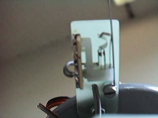
The light sensor controller is, like the tsc above, used for
implementing simple and fundamental behaviors. Based on a simple cds it measures ambient
light by rotating the photo cell 180 degree from the left to the right in steps of 30°.
This readings are then the basis for any behavioral algorithms.
The propram runs as a task in the spu.
See here a photo of the sensor on its rotating
carrier.
The proprioceptive sensor controller measures only the levels of the two supply voltages for both digital and analogous circuitry. Though not implemented yet, it is designed, built-up and read for use. It continously measures the voltage levels and pulls an input port on the master control processor to low (some sort of interrupt) to indicate a low-voltage condition. The mcp then performs a proper action (visit the next charger or so).
The navigation and path planning processor actually is the heart of Aachnae. It creates
a topographical map based on the range data coming from the ultra sonic
range detector subsystem. Since even a Basic Stamp 2/SX isn't powerful enough neither
to hold such a large dataset needed for maps nor to perform a suitable path planning a pc
is used for this job. It is planned for a future revision of the control system to use a
single board pc (possibly equipped with flash disk(s)) mounted on arachnae to to the map
processing onboard. At the moment all data from the range detection system are transmitted
on a serial line to the pc which performs both the map generation and path planning. The
outcomes of this process are sent back to the robot where they are the basis for gait
adjustments and step sequence calculations.
This feature is fixed part of the next revision of the control system.
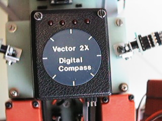
The digital compass is a sensor subsystem which is primarily based on the 2-axis
compass and magnetic sensor module from Precision
Navigation, Inc. It is controlled by a Basic Stamp 2 microcomputer due to the high
computing constraints and high number of I/O pins needed. Its is programmed to output
heading (also called yaw or azimuth) in bcd format with a resolution of 1° which seems to
be really enough for this application.
See here a photo of the compass.
![]()
![]()
![]()
![]()
![]()
![]()
Last updated: 26.6.1999