


Final Report: Arachnae II
Design Overview |
The following paragraphs give a brief description of Arachnae's mechanical
and electrical design constraints.
All of these come from the experiences with the predecessor of Arachnae II, the six-legged
walker Arachnae I (designed by Edmund Schierer).
It was considerably limited in its mobility due to the restriction to 2 DOF per leg (which
results in a total DOF of only 15) and maximum payload due to the low-powered gear-motors.
Mechanics |
Click on image to get a more detailed description of the selected part.
Based on the experiences with Arachnae I the robot's body is designed as a H-shaped frame of laminated wood. This material and profile guarantees both lightweight and high bending strength.
Though there's actually no head and tail in this design, the front of the robot is determined by a bunch of tactile sensors (these are whiskers-like wires mounted at one end of the frame).
Swing and Lift servos form the minimum number of 2 for a leg's degree of freedom. This
servo moves a leg forward and backward.
Should be carefully selected because one servo must be strong enough to move the whole
robot.
Responsible for the second DOF of a leg (lift and drop). This is the most critical electrical/mechanical part because these six servos carry the total weight of the robot. A rule of thumb is, that one servo shall be able to carry half the weight of the robot.
This joint forms a third degree of freedom for a leg. It is not only used for more flexibility on avoiding obstacles in the footpath/trajectory of a leg but also for the ability to climb over obstacles up to the height of the robot.
The design of the legs is inspired by and kinematically similar to those of insects (more or less).
The body-coxa joint is (differing from insects) actually formed by two joints, each driven by a separate servo, resulting in a 2 DOF connection of the leg to the robot's frame. The third DOF comes from an extra servo driving a knee-joint. This plus the 3 DOF of the frame gives Arachnae a total DOF of 21.
Electronics |
The electronics is formed by a bunch of microcontrollers of different performance connected together in a layered serial network and analog circuitry for sensors and motor drivers.
Click on the next image to get a brief description of any of the single nodes.
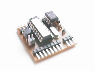
The MCP is a node processor, responsible for network initialization, administration and message scheduling. For its low performance constraints it is realized with a BS1, a tiny controller based on a Microchip PIC 16C56.
The MMC performs gait controlling tasks, that is, he receives global 'direction' commands from the NP3 and calculates practical step sequences which he finally sends to the subordinated leg processors. As a result of the expected high demands for performance a Basic Stamp 2/SX computer is used.
The NP3 builds up a topological map based on sonar it data from the USRC and calculates an optimal path through the environment. This task requires really high high computing power, so it is done externally on a PC.
Each of the six legs is controlled by its own subprocessor. It gets gait commands from the MMC and calculates an according trajectory.
The SPU is a coordination processor for all the individual sensor subsystems of Arachnae II. It gets data from and distributes transmission requests to the several sensors. An additional task is administering the sensor network, that is, testing all the received sensor data for correctness and accuracy and, if necessary, to take a sensor subsystem out of order, if it is supposed to work improperly.
Ultra Sonic is, besides Laser Range Scanners, the best choice for range detection. It
is inexpensive and accurate enough especially for those applications described here. Due
to resolution constraints (res = 2 cm) a Basic Stamp 2 is sufficient in its computing
power.
Effective maximum range of detection is limited to 8m. Arachnae II uses the USRC data for
map generation which is further the basis for a subsequent navigation and
path planning.
This sensor subsystem is, like the USRC above, a range detecting unit. In constrast to this, it is only used for short range measurements up to 80 cm. The intended purpose is mainly detection of near obstacles and collision avoidance. It supports the USRC in cases, when this sensor fails (maximum runtime of sonar 'ping' exceeded or nonreflecting/sound-absorbing materials in the environment).
The TPSC actually consists of a bunch of whiskers-like feelers for collision detection. Tough this function has hard real-time requirements it runs sufficiently as a task in a BS2/SX.
A robot moving in natural terrain may find itself in situations where inclination becomes dangerous or results in malfunctions. An inclination sensor is used to prevent such unpleasant occurences.
Insect-like/real-life behavior includes besides a lot of others proper response to external influences like ambient temperature or light. Due to the inertia of temperature two sensors are used for easy and fast detection of differences in temperature
Light is the second physical parameter used for implementing insect-like behavior on Arachnae II. Cause' light sensors normally are much faster than those for temperature a single sensor mounted on a rotating platform may be used.
A PSC in robotics normally comprises all the sensory required for proper operation of the basic mobility functions like motor/gear temperatures and voltage level of power supply. Arachnae II 's PSC only monitors both the voltage level of the power supply for motors and controller network.
The digital compass V2X transmits its data to the NP3, where they are used both to determine the orientation of the robot in the environment and to calculate according 'change direction'-commands to be sent to the MMC. Due to the expensive calculation of the compass heading a BS2 is used exclusively for the V2X.
![]()
![]()
![]()
![]()
![]()
![]()
Last updated: 26.6.1999
